§150.2(a)1C, and §150.2(a)2C
As residential buildings have been tightened over the last several code cycles to improve energy performance, the dilution of indoor air through natural ventilation has been significantly reduced. As a result, the importance of controlling indoor pollutants generated by kitchen ranges during food preparation and from common building materials, cleaners, finishes, packaging, furniture, carpets, clothing, and other products has increased. Energy Commission-sponsored research has revealed that concentration of pollutants such as formaldehyde are higher than expected, and that many occupants do not open windows regularly for ventilation. The 2019 Energy Standards include requirements for mandatory mechanical ventilation intended to improve indoor air quality (IAQ) in homes, and requirements for MERV 13 air filtration on space conditioning systems, and ventilation systems that provide outside air to the occupiable space of a dwelling.
As specified by §150.0(o), single-family detached dwelling units, and multifamily attached dwelling units must meet the requirements of ASHRAE Standard 62.2-2016 including Addenda b, d, l, q, and s (ASHRAE 62.2), subject to the amendments specified in Section 150.0(o)1. A copy of this version of ASHRAE 62.2 may be obtained at the following URL:
[insert link to ASHRAE bookstore for this version of ASHRAE 62.2 when it becomes available]
Opening and closing windows and continuous operation of central fan-integrated ventilation systems are not allowable options for meeting dwelling unit ventilation requirements. The requirements of ASHRAE Standard 62.2 focus on providing continuous dwelling unit mechanical ventilation, as well as local exhaust ventilation at known sources of pollutants or moisture, such as kitchens, bathrooms, and laundries.
Limiting the sources of indoor pollutants is one important method for protecting indoor air quality. Kitchen ranges used for preparation of food have been identified as a source of indoor air pollution that must be addressed, and builders should adhere to the requirements of Section 4.504 of the California Green Building Standards Code for the selection of materials and finishes that have no or low emissions of air pollutants such as formaldehyde and volatile organic compounds (VOCs). The California Air Resources Board (CARB) also provides guidance for reducing indoor air pollution in homes. For more information, see the CARB Indoor Air Quality Guidelines:
http://www.arb.ca.gov/research/indoor/guidelines.htm
This section will cover compliance and enforcement, typical design solutions, energy consumption issues, and other requirements specified by ASHRAE 62.2 as amended in the 2019 Title 24 standards. The key changes in the adopted 2016 version of ASHRAE 62.2 and Title 24 Part 6 amendments to 62.2 include the following:
1. ASHRAE 62.2 now covers mid-rise and high-rise residential occupancies, as well as single-family detached and low-rise attached multifamily dwellings.
2. For single-family homes, the standard requires higher rates of dwelling unit mechanical ventilation than previously. An adjustment to the ventilation rate is provided to account for the effects of the envelope infiltration, which varies by climate zone (Table 4-14). Homes sealed to a leakage rate of less than 2 ACH50 will require larger fans to compensate for the decrease in effective ventilation due to infiltration.
3. Single-family detached dwellings and townhomes using balanced ventilation systems will require lower ventilation rates as compared to the rates required when exhaust or supply-only ventilation is used.
4. Compliance with required dwelling unit ventilation using variable mechanical ventilation systems (intermittent or variable operation) requires the average mechanical ventilation rate (in CFM) over a three-hour period to be greater than or equal to the ventilation rate used for continuous ventilation. Otherwise, more complicated control strategies may be used if the system operation complies with the “relative exposure” calculations in normative Appendix C of ASHRAE 62.2.
5. Two options for compliance with dwelling unit ventilation are allowed for multifamily attached dwelling units: (1) installation of a balanced ventilation system or (2) installation of an exhaust or supply-only system accompanied by sealing to a leakage rate of not more than 0.3 CFM50 per ft2 of dwelling unit enclosure surface area.
6. Kitchen range hood fans are now required to be verified by a HERS Rater. The new verification protocol requires comparing the installed model to ratings in the Home Ventilating Institute (HVI) directory of certified ventilation products to confirm the installed range hood is rated to meet the required airflow and sound requirements specified in ASHRAE 62.2. See section 4.6.7 below for more detail. Kitchen range hood fans that exhaust more than 400 CFM at minimum speed are exempt from this requirement.
Compliance with the dwelling unit ventilation airflow specified in ASHRAE 62.2 is required in new dwelling units, in new dwelling units that are additions to an existing building, and in additions to existing dwelling units that increase the conditioned floor area of the existing dwelling unit by more than 1,000 square feet. Alterations to components of existing buildings that previously met any requirements of ASHRAE 62.2 must continue to meet requirements upon completion of the alteration(s).
The following summarizes the key requirements for most newly constructed buildings:
1. A dwelling unit mechanical ventilation system shall be provided. Typical solutions are described in Section 4.6.2 below. The airflow rate provided by the system shall be confirmed through field verification and diagnostic testing in accordance with the applicable procedures specified in Reference Residential Appendix RA3.7.
2. Kitchens and bathrooms shall have local exhaust fans vented to outdoors.
3. Clothes dryers shall be vented to outdoors.
Miscellaneous indoor air quality design requirements also apply, including the following:
1. Ventilation air shall come from outdoors and shall not be transferred from adjacent dwelling units, garages, unconditioned attics or crawl spaces.
2. Ventilation system controls shall be labeled, and the homeowner shall be provided with instructions on how to operate the system.
3. Combustion appliances shall be properly vented, and exhaust systems shall be designed to prevent back drafting.
4. Walls and openings between the house and the garage shall be sealed or gasketed.
5. Habitable rooms shall have windows with an opening ventilation area of at least 4 percent of the floor area.
6. Mechanical systems including heating and air-conditioning systems that supply air to habitable spaces shall have MERV 13 filters or better and be designed to accommodate the rated pressure drop of the system air filter at the designed airflow rate.
7. Dedicated air inlets (not exhaust) that are part of the ventilation system design shall be located away from known sources of outdoor contaminants.
8. A carbon monoxide alarm shall be installed in each dwelling unit in accordance with NFPA Standard 720.
9. Air-moving equipment used to meet the dwelling unit ventilation requirement and the local ventilation exhaust requirement shall be rated in terms of airflow and sound:
a. Dwelling unit ventilation and continuously operating local exhaust fans must be rated at a maximum of 1.0 sone (measurement of sound).
b. Demand-controlled local exhaust fans must be rated at a maximum of 3.0 sone.
c. Kitchen exhaust fans must be rated at a maximum of 3.0 sone at one or more airflow settings greater than or equal to 100 CFM.
d. Remotely located air-moving equipment (mounted outside habitable spaces) are exempt from the sound requirements provided there is at least 4 feet of ductwork between the fan and the interior grille.
Compliance with ASHRAE 62.2 requirements must be verified by the enforcement agency, except for the following requirements that must be HERS verified in accordance with the procedures in Residential Appendix RA3.7:
•Dwelling unit ventilation airflow rate
•HVI ratings for kitchen range hood fans
All applicable certificates of compliance, installation, and verification must be registered with an approved HERS Provider.
Title 24 Part 6 amendments to ASHRAE 62.2 eliminated the requirement to use the result of a blower door measurement when calculating the required dwelling unit mechanical ventilation rate (Qfan). Instead, the Qfan calculation applies a default infiltration leakage rate equivalent to 2 ACH50. Blower door testing to measure actual dwelling unit enclosure leakage is required only when performance compliance modeling uses an infiltration leakage rate less than 2 ACH50 - which requires HERS verification of dwelling unit enclosure leakage for energy compliance as well as for determining Qfan.
If a central heating/cooling system air-handler fan is used to ventilate the dwelling (central fan-integrated ventilation, also known as CFI ventilation), the air-handler must meet or exceed the mandatory fan efficacy criteria. This requires the installer to perform the test given in Reference Appendix RA3.3 and a HERS Rater to verify the efficacy (W/CFM) of the air-handling unit fan.
4.6.1.1 Certificate of Compliance Reporting Requirements
When using the prescriptive compliance approach, the mechanical ventilation rate (Qfan) must be manually calculated using the applicable equations in Standards Section 150.0(o)1, also shown in Section 4.6.4 below. The value for Qfan is required to be reported on the CF1R. When using the performance method, the compliance model automatically calculates Qfan based on the inputs for conditioned floor area, number of bedrooms, and climate zone (Table 4-14), and uses the Qfan ventilation airflow value when calculating the building energy use. The performance certificate of compliance (CF1R) will report the:
1. Minimum mechanical ventilation airflow rate (calculated value) that must be delivered by the system.
2. Type of ventilation system (exhaust, supply, balanced, CFI).
3. Fan efficacy (W/CFM) for the selected system.
4. Recovery efficiency (%) (applicable to HRV/ERV system types only)
5. For CFI systems--HERS verification of air handler fan efficacy is required.
The installed dwelling unit ventilation system must conform to the performance requirements on the CF1R.
The enforcement agency may require additional information/documentation describing the ventilation systems be submitted along with the CF1R at plan check.
4.6.1.2 Certificate of Installation and Certificate of Verification Reporting Requirements
The builder/installer must complete certificates of installation (CF2R-MCH-01 and CF2R-MCH-27) for the dwelling. The HERS Rater must complete a certificate of verification (CF3R-MCH-27) for the dwelling.
The following information must be provided on the CF2R-MCH-01 to identify each ventilation system/fan in the dwelling that will require HERS verification.
For dwelling unit ventilation systems:
1. Ventilation system name or identification
2. Ventilation system location
3. Ventilation system control type (i.e. continuous, variable)
4. Ventilation system type (i.e. exhaust, supply, balanced, CFI).
5. Ventilation system target airflow rate (may be less than Qfan if using multiple systems/fans to comply)
6. Ventilation system manufacturer name
7. Ventilation system model number
8. Control system manufacturer (if applicable)
9. Control system model number (if applicable)
10. Energy Commission certification number for variable system/control (if applicable)
For kitchen exhaust ventilation systems:
1. Kitchen exhaust control type (i.e. demand-controlled, continuous)
2. Kitchen exhaust system type (i.e. range hood, over the range (OTR) microwave, downdraft, local exhaust, other).
3. Kitchen exhaust system required airflow rate
4. Kitchen exhaust system manufacturer name
5. Kitchen exhaust system model number
6. Kitchen exhaust system HVI certification number
The following additional information must be provided on the CF2R-MCH-27 to document compliance with §150.0(o). Refer also to the procedures in RA 3.7.4.
For dwelling unit ventilation systems:
•Measured airflow rate of the installed dwelling unit ventilation system. For balanced systems, exhaust and supply airflows must be measured and recorded.
For kitchen exhaust ventilation systems:
•Confirmation the installed system is rated by HVI to meet the required airflow and sound requirements.
For all ventilation systems:
•Confirmation that the other applicable requirements given in Sections 6 and 7 of ASHRAE 62.2 as amended in §150.0(o)1 have been met (see Sections 4.6.7 and 4.6.8 below).
The following additional information must be provided on the CF3R-MCH-27 to document compliance with §150.0(o):
For dwelling unit ventilation systems:
•Measured airflow rate of the installed dwelling unit ventilation system. For balanced systems, both exhaust and supply airflows must be measured and recorded.
For kitchen exhaust ventilation systems:
•Confirmation the installed system is rated by HVI to meet the required airflow and sound requirements.
From ASHRAE 62.2, Section 4.2,System Type.
The dwelling-unit mechanical ventilation system shall consist of
one or more supply or exhaust fans and associated ducts and controls. Local
exhaust fans shall be permitted to be part of a mechanical exhaust system. Where
local exhaust fans are used to provide dwelling-unit ventilation, the local
exhaust airflow may be credited toward the dwelling-unit ventilation airflow
requirement. Outdoor air ducts connected to the return side of an air handler
shall be permitted as supply ventilation if manufacturers’ requirements for
return air temperature are met.
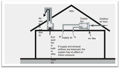
There are four typical solutions for meeting the dwelling unit outside air ventilation requirement:
1. Exhaust ventilation - air is exhausted from the dwelling unit and replaced by infiltration.
2. Supply ventilation - outdoor air is supplied directly to the dwelling unit after being filtered.
3. Central fan-integrated ventilation - outdoor air is ducted to the return plenum of the central space conditioner air handler. Both return air and outdoor air must be filtered.
4. Balanced ventilation – may be a single packaged unit containing supply and exhaust fans that move approximately the same airflow through a heat or energy recovery core, or may use separate fans without heat exchange. In both cases, air supplied from outdoors must be filtered. (See Section 4.4.1.14 for filter requirements.)
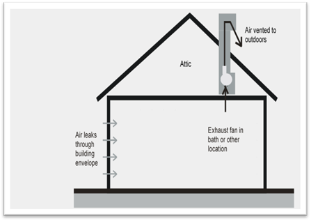
4.6.2.1 Exhaust Ventilation
Exhaust ventilation is typically provided using a quiet, continuously operating ceiling-mounted fan or attic-mounted inline fan. Air is drawn from the house or unit and exhausted to the outdoors. Outdoor air enters the house or unit through infiltration. Many high-quality, quiet fans are available for this purpose. For larger homes, more than one fan may be used. The same fan can be used to meet dwelling unit and local (bathroom or laundry) exhaust ventilation requirements. Inline fans can be used to exhaust air from one or more bathrooms. Remotely located fans (fans mounted outside habitable spaces) are exempt from the sound requirements if there is at least 4 feet of ductwork between the fan and the interior grille.
Figure 4-28: Exhaust Ventilation Example
Source: California Energy Commission
4.6.2.2 Supply Ventilation
Supply ventilation systems draw outdoor air into the house using a dedicated supply fan and most likely distribute ventilation air through supply ductwork, although that is not a requirement. Indoor air escapes through leaks in the building envelope (exfiltration), as shown in Figure 4-29. For larger homes, more than one fan may be used. Remotely located fans (fans mounted outside habitable spaces) are exempt from the sound requirements if there is at least 4 feet of ductwork between the fan and the interior grille. Thus, if less than 4 feet of ductwork are used, the supply fan must meet the maximum 1.0 sone rating requirement for dwelling unit ventilation fans.
Figure 4-29: Supply Ventilation Example
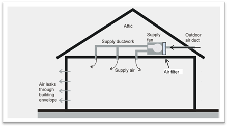
Source: California Energy Commission
Section 150.0(m)12 requires that outside air be filtered using MERV 13 (or greater) particle removal efficiency rated air filters. The filters must be accessible to facilitate replacement. Supply systems may locate the MERV 13 air filter either upstream or downstream of the fan as long as the incoming outdoor air is filtered prior to delivery to the dwelling unit habitable space. Fans may be located in attics, dropped ceiling spaces, or other spaces dedicated for installation of mechanical equipment.
The outdoor air inlet should be located to avoid areas with contaminants such as smoke produced in barbeque areas and products of combustion emitted from gas appliance vents. Air may not be drawn from attics or crawlspaces. To minimize drafts and optimize distribution, supply air can be ducted directly to bedrooms and living areas using an appropriately sized and sealed ventilation-only duct system or by connecting to the HVAC supply plenum.
4.6.2.3 Central Fan-Integrated (CFI) Ventilation
The central forced-air system air handler can be configured to function as a ventilation supply system by installing an outdoor air duct that connects the return plenum of the air-handler to outdoors. This strategy, called CFI ventilation, uses negative pressure in the return plenum to draw in outdoor air, which is mixed and distributed with a larger volume of return air from the house. A motorized damper and special CFI controls must be installed to ensure the air handler delivers the required ventilation airflow regardless of whether the heating/cooling system operates to provide space conditioning. Thus, when the heating/cooling operating time is reduced during times when space conditioning is not needed, the CFI controls will operate only the system fan and outdoor air damper to provide ventilation air even if space conditioning is not needed. Because of the relatively high energy use of the central system fan, CFI systems consume greater amounts of energy compared to exhaust or supply or balanced ventilation systems. Continuous operation of the CFI air handler fan to provide the required dwelling unit ventilation is prohibited.
Figure 4 30: Central Fan-Integrated (CFI) Ventilation Example
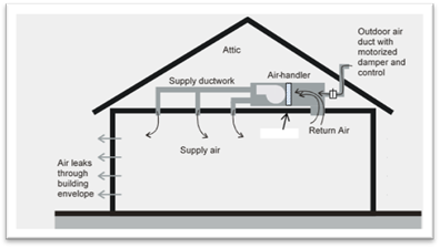
Source: California Energy Commission
Section 150.0(m)12 requires that outside air be filtered using MERV 13 (or greater) particle removal efficiency rated air filters. Filters must be accessible to simplify replacement. For CFI systems, the filters must be installed upstream of the cooling or heating coil; thus, the filter rack provided at the inlet to the air handler may be used. Otherwise, filters must be provided at the return grill(s) for the central fan, and another filter must be provided in the outside air ductwork before the point the outside air enters the return plenum of the central fan.
When considering system design and HERS verification compliance for CFI ventilation systems, it is important to distinguish between the central forced-air system fan total airflow and the much smaller outdoor ventilation airflow rate (the airflow that is induced to flow into the return plenum from outdoors). Both of these airflows must be verified by a HERS Rater. Refer to Figure 4-30 and note that the total airflow through the air handler is the sum of the return airflow and the ventilation airflow.
CFI ventilation systems, devices, and controls may be approved for use for compliance with the HERS field verification requirements for dwelling unit mechanical ventilation airflow. CFI ventilation systems must be automatically controlled by a timer or other device that assures they will operate the minimum amount of time needed to meet the ventilation requirement. The scheduling of the automatic controls must be such that the fan operates at least once every three hours and the average dwelling unit ventilation rate over any 3-hour period must be greater than or equal to the required ventilation rate Qfan calculated using the applicable equations in Standards §150.0(o)1 (also shown in Section 4.6.4 below).
Section §150.0(o)1B specifically prohibits continuous operation of the central forced-air system of a CFI ventilation system, so CFI ventilation systems must operate intermittently and be certified to the Energy Commission as an intermittent or variable system that will meet the minimum ventilation airflow required by §150.0(o).
A listing of certified CFI ventilation systems is posted at the following URL:
http://www.energy.ca.gov/title24/equipment_cert/imv/
The outside air ducts for CFI ventilation systems are not allowed to be sealed/taped off during duct leakage testing. However, CFI outdoor air ductwork that uses controlled motorized dampers that open only when outdoor air ventilation is required and close when outdoor air ventilation is not required may be closed during duct leakage testing.
Because CFI ventilation systems can use a large amount of electricity annually compared to other ventilation system types, the air handlers used in CFI ventilation systems are required to meet the fan watt draw requirements given in Section 150.0(m)13B in all climate zones.
4.6.2.4 Balanced Ventilation
Balanced systems use an exhaust fan and a supply fan to move approximately the same volume of air into and out of the dwelling. To be considered a balanced ventilation system, the total supply airflow and the total exhaust airflow must be within 20 percent of each other. For determining compliance, the average of the supply and exhaust airflows is equal to the balanced system airflow rate. (Refer to RA3.7.4.1.2.)
Some balanced systems are small packaged systems that include heat exchangers that temper incoming air with outgoing air, which reduces the thermal effect of ventilation on heating and cooling loads, but the dual fans also increase electrical energy use. They are most practical for use in tightly sealed houses and in multifamily units where exhaust type systems have difficulty drawing adequate outside air due to limited exterior wall area.
Like supply ventilation systems, balanced systems are required to be equipped with MERV 13 or better filters to remove particles from outside airflow. An example of a heat recovery ventilator is shown in Figure 4-31.
The outdoor air inlet should be located to avoid areas with contaminants such as smoke produced in barbeque areas and products of combustion emitted from gas appliance vents. Air may not be drawn from attics or crawlspaces.
Figure 4-31: Balanced Ventilation Example 1 – HRV or ERV
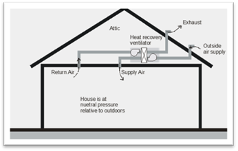
Source: California Energy Commission
Another balanced system configuration uses a stand-alone supply fan coupled with a stand-alone exhaust fan, both wired to a common switch or control to ensure they operate simultaneously. The controls must make it possible to adjust the speed of the fans for balancing the airflows. An example is shown in Figure 4-32.
Figure 4-32: Balanced Ventilation Example 2 – Separate Supply and Exhaust Fan
Source: California Energy Commission
4.6.3.1 System Types
There are generally three system types available for meeting the dwelling unit ventilation requirement (refer to Section 4.6.2 for descriptions of the system types described below):
1. Exhaust ventilation – air is exhausted from the dwelling unit and replaced by infiltration.
2. Supply ventilation – outdoor air is supplied directly to the dwelling unit after being filtered.
3. Balanced ventilation – may be a single packaged unit containing supply and exhaust fans that moves approximately the same airflow through a heat or energy recovery core or may use separate fans without heat exchange. In both cases, air supplied from outdoors must be filtered. (See Section 4.4.1.14 for air filter requirements.)
Exhaust and balanced systems are most frequently used in multifamily buildings, but supply ventilation may also be used. Exhaust (or supply) systems in low-rise buildings typically use fans located in the dwelling units that exhaust directly to the outdoors.
4.6.3.2 Multifamily Building Central Shaft Ventilation Systems
Use of central ventilation fans/shafts that are shared with multiple dwelling units in the building are more common in mid-rise and high-rise buildings. When a supply or exhaust system provides dwelling unit ventilation to more than one dwelling unit, the airflows in each dwelling unit must be equal to or greater than the required (minimum) ventilation rate, and the airflows for each dwelling unit must also be balanced to be no more than 20 percent greater than the specified rate (See Standards §150.0(o)1F). The specified rate for the systems that share a common fan/shaft may be the minimum rate required for compliance, in which case each of the dwellings receiving airflow from a common fan/shaft must have ventilation airflow no more than 20 percent greater than the minimum dwelling unit ventilation airflow required by Equation 150.0-B. If the lowest airflow provided to any of the dwellings served by the common fan/shaft is a specific percent value greater than the minimum required for compliance, then the each of the dwellings receiving airflow from that common fan/shaft must have ventilation airflow no more than 20 percent greater than that lowest dwelling unit ventilation airflow. For example, if the lowest ventilation airflow among all dwellings served by the common fan/shaft is 2 percent greater than the minimum required for compliance, then all dwellings served by the common fan/shaft must be balanced to have ventilation airflow that is no more than 22 percent greater than the minimum ventilation airflow required for compliance.
These systems must use balancing devices to ensure the dwelling-unit airflows can be adjusted to meet this balancing requirement. These system balancing devices may include, but are not limited to, constant air-regulation devices, orifice plates, and variable-speed central fans.
Since supply and exhaust ventilation system types are required to operate continuously in multifamily dwellings (see §150.0(o)1Eii), and since CFI systems are prohibited from operating continuously to provide the required dwelling unit ventilation (see §150.0(o)1B), the CFI ventilation system type is not allowed to be used in multifamily dwellings.
4.6.3.3 Multifamily Dwelling Unit Compartmentalization – Reducing Dwelling Unit Enclosure Leakage
Transfer air is the airflow between adjacent dwelling units in a multifamily building that can be a major contributor to poor indoor air quality in the dwelling units. Transfer airflow is caused by differences in pressure between adjacent dwelling units that force air to flow through leaks in the dwelling unit enclosure. The pressure differences may be due to stack effects and wind effects, but unbalanced mechanical ventilation is also a major contributor to this problem. It is desirable to minimize or eliminate leaks in all the dwelling enclosures in the building – to compartmentalize the dwellings - to prevent pollutants such as tobacco smoke, pollution generated from food preparation in the kitchen, odors, and other pollutants from being transferred to adjacent dwellings in the building.
Title 24 provides two compliance paths for mechanical ventilation which improve compartmentalization in multifamily buildings (choose one):
1. Install a balanced ventilation system. This may consist of either a single ventilation unit (such as an ERV or HRV) or may consist of separate supply and exhaust fans that operate simultaneously and are controlled to balance the supply and exhaust airflows. The outdoor ventilation supply air must be filtered (MERV 13 or better).
2. Verify that the dwelling unit leakage is not greater than 0.3 CFM per ft2 of dwelling unit enclosure area using the procedures in RA3.8 (blower door test). If the dwelling unit enclosure passes this blower door test, use of continuously operating supply ventilation systems, or continuously operating exhaust ventilation systems in that dwelling is allowed.
Residential Appendix RA 3.7.4 provides direction for measurement of supply, exhaust, and balanced system types. These measurement procedures are applicable when there is a fixed airflow rate required for compliance, such as for systems that operate continuously at a specific airflow rate or systems that operate intermittently at a fixed speed (averaged over any three-hour period), according to a fixed timer pattern for which the programmed pattern is verifiable by a HERS Rater on site. (Refer to ASHRAE 62.2 Section 4.5.1 Short Term Average Ventilation.)
Variable or intermittent operation that complies with ASHRAE 62.2 Sections 4.5.2 and 4.5.3 complies with the dwelling unit mechanical ventilation requirements by use of varying ventilation airflow rates based on complicated calculations for relative exposure as specified in ASHRAE 62.2 Normative Appendix C. These calculation procedures provide the basis for "smart" ventilation controls implemented by use of digital controls that rely on the manufacturer's product-specific algorithms or software. Any ventilation system models that use these complex ventilation system controls in a ventilation product designed to be used to comply with Standards §150.0(o) must submit an application to the Energy Commission to have the ventilation technology approved. These manufacturers are expected to provide with their applications evidence that the system will perform to provide the required dwelling unit mechanical ventilation. The manufacturers are also expected to provide a method that could be used by a HERS Rater to verify that an installed system is operating as designed.
Listings of systems approved by the Energy Commission and certified by the manufacturer are located at the following URL:
http://www.energy.ca.gov/title24/equipment_cert/imv/
Dwelling unit ventilation systems may operate continuously or on a short-term basis. If fan operation is not continuous, the average ventilation rate over any three-hour period must be greater than or equal to the Qfan value calculated using the equations in this section.
ASHRAE 62.2 provides for scheduled ventilation and real-time control, but these control approaches require “equivalent exposure” calculations using methods in Normative Appendix C, and complex controls would be required to operate the fan.
Equations for calculating Qfan (the required mechanical ventilation rate) for both single- and multifamily buildings are listed below. Single-family detached dwelling units and attached dwelling units not sharing ceilings or floors with other dwelling units, occupiable spaces, public garages, or commercial spaces (e.g. duplexes and townhomes) are allowed to take credit for the building infiltration in the calculations as described below. Use of a building infiltration credit is not applicable to calculation of the required dwelling unit mechanical ventilation for multifamily dwelling units.
A new aspect of the ventilation calculations for the 2019 standards is that the building infiltration rate (Qinf) varies by climate zone (Table 4-14) and building height. Therefore, the value for Qfan for a single-family dwelling or townhome will also vary based on climate zone and building height.
When the performance compliance approach is used, the compliance software completes all the calculations given in Equations 4-1, 4-2, 4-3, and 4-4, and Qfan is reported on the CF1R. If the prescriptive compliance approach is used, the Data Registry will perform the calculations, and the value for Qfan will be recorded on the CF1R.
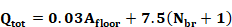
4.6.5.1 Total Ventilation Rate (Qtot)
The total ventilation rate is the combined volume of ventilation air provided by infiltration and the mechanical ventilation provided from fans, as follows:
Equation 4-1
Where:
Qtot = total required ventilation rate (CFM)
Afloor = conditioned floor area (ft2)
Nbr = number of bedrooms (not less than one)
For multifamily units, the installed ventilation system must deliver the total ventilation rate Qtot calculated from Equation 4-1.
4.6.5.2 Infiltration Rate (Qinf)
For single-family homes, when determining the required dwelling unit mechanical ventilation airflow rate (Qfan in Equation 4-4), the calculated value for estimated infiltration rate (Qinf in Equation 4-2) is deducted from the value of Qtot (determined by Equation 4-1). The calculated value for estimated infiltration rate depends on the building leakage, building height, and the weather and shielding factor, which varies by climate zone (Table 4-14). A default envelope leakage value of 2 ACH50 is mandatory for the fan sizing calculations unless a blower door measurement is performed that determines a leakage rate below 2 ACH50. Leakage in ACH50 must be converted to CFM50 for use in subsequent calculations. Conversion of 2 ACH50 is shown in Equation 4-2.
Equation 4-2
Q50 = Vdu x 2 ACH50)/ 60
Where:
Q50 = leakage rate at 50 Pa, CFM
Vdu = dwelling unit conditioned volume, ft3
ACH50 = air changes per hour at 50 Pa (0.2 inch water)
Vdu can be approximated by multiplying the average ceiling height by the dwelling conditioned floor area. If the field-verified value for ACH50 is less than 2, then the verified value is used in Equation 4-2 instead of 2.
The effective annual infiltration rate (Qinf), is calculated using the weather/shielding factor (wsf) for the applicable climate zone and the building height. See Table 4-14 below and Standards Table 150.0-D for values for wsf.
Equation 4-3
Qinf = 0.052 x Q50 x wsf x [H/Hr]2 (CFM)
Where:
Qinf = effective annual infiltration rate, CFM
Q50 = leakage rate at 50 Pa, CFM
wsf = weather and shielding factor from Table 4-14
H = vertical distance between the lowest and highest above-grade points within the pressure boundary
Hr = reference height = 8.2 ft
The number of stories multiplied by the average ceiling height (as entered in compliance software) provides sufficient accuracy for determining H.
|
CZ |
WSF |
CZ |
WSF |
|
1 |
0.56 |
9 |
0.39 |
|
2 |
0.49 |
10 |
0.42 |
|
3 |
0.54 |
11 |
0.50 |
|
4 |
0.48 |
12 |
0.51 |
|
5 |
0.52 |
13 |
0.45 |
|
6 |
0.45 |
14 |
0.58 |
|
7 |
0.40 |
15 |
0.45 |
|
8 |
0.36 |
16 |
0.44 |
4.6.5.3 Required Mechanical Ventilation Rate (Qfan)
The required mechanical ventilation rate, Qfan is the total outside airflow required to be supplied to (or total indoor air required to be exhausted from) the building by fans. Balanced ventilation system types must provide an average of the supply and exhaust airflows that is greater than or equal to Qfan.
Qfan is calculated using Equation 4-4 below, which uses the values for Qtot and Qinf determined above. Equation 4-4 accounts for reduced exterior wall leakage area in attached units (e.g. townhomes and duplexes). Equation 4-4 also accounts for the differences in ventilation effectiveness of balanced systems compared to exhaust/supply (unbalanced) systems due to varying dwelling infiltration leakage rates. If Qfan is less than 10 CFM, then no fan is required.
Equation 4-4
Qfan = Qtot - Φ ( Qinf x Aext)
Where:
Q_total = total required ventilation rate (CFM)
Q_inf = effective annual average infiltration rate (CFM)
Φ = 1 for balanced ventilation systems or Qinf/Qtot for other system types
Aext = 1 for single-family detached homes. For attached dwelling units not sharing ceilings or floors with other dwelling units, occupiable spaces, public garages, or commercial spaces (e.g. duplexes and townhomes), Aext is the ratio of exterior envelope surface area that is not attached to garages or other dwelling units to total envelope surface area.
For multifamily dwelling units, Qfan = Qtot.
Example 4-11 – Required Ventilation
Question:What is the required continuous ventilation rate for a three-bedroom, 1,800 ft² townhouse located in Climate Zone 8 that has 9-foot ceilings, and where 25% of the exterior wall surface area adjoins another unit? Ventilation is provided by a bathroom exhaust fan. No extraordinary measures have been taken to seal the building.
Answer:
Equation 4-1 yields a total ventilation rate of 84 CFM
Qtot= 0.03Afloor + 7.5(Nbr+1) = 0.03(1800) + 7.5(3+1) = 84 CFM
The volume is 1,800 x 9 = 16,200 ft3. Solving for Equation 4-2 results in a leakage rate of 543 CFM
Q50 = Vdu x 2 ACH50/ 60 = 16,200 x 2/60 = 540 CFM
Using Equation 4-3: Qinf = 0.052 x Q50 x wsf x [H/Hr]z = 0.053 x 540 x 0.36 x (18/8.2)0.4 = 14 CM
And applying Equation 4-4, the mechanical ventilation system must move 82 CFM.
Qfan = Qtot - Qinf/Qtot (Qinf x Aext) = 84 – 13.8/84(13.8 x (1-0.25) = 82.3 CFM
Due to the reduction in infiltration resulting from reduced exterior wall area and to the use of an exhaust fan instead of a balanced system, the effective infiltration credit is only 2 CFM.
Example 4-12
Question:
The two-story house I am building in Climate Zone 12 has a floor area of 2,240 ft² and four bedrooms. I am using an HRV that delivers 80 CFM of outdoor air and exhausts 90 cfm of indoor air. My calculations come out to 86 CFM. Can I use this system?
Answer:
No. For balanced systems, the supply and exhaust airflows can be averaged, and in this case, they average 85 CFM, which is slightly less than the required 86 CFM.
The nominal rating of a fan can be different than what it actually delivers when installed and connected to ductwork, so designers should always include a safety margin when sizing equipment. The length and size of ducting should be used to calculate the pressure drop. This is why dwelling unit ventilation rates must be verified by a HERS Rater.
Example 4-13
Question:
A 2,300 ft² house has exhaust fans running continuously in two bathrooms, providing a total exhaust flow rate of 90 CFM, but the requirement is 98 CFM. What are the options for providing the additional 8 CFM?
Answer:
Option 1: The required additional CFM could be provided either by increasing the size of either or both exhaust fans such that the combined airflow exceeds 98 CFM.
Option 2: Another solution would be to use a balanced system, which may reduce the airflow requirement to below 90 CFM. Adding another 8 CFM fan is not an acceptable solution.
Example 4-14
Question:
A CFI system is connected to the return air plenum of a furnace such that when operating, 10% of the air supplied by the furnace is outdoor air. The CFI control limits furnace fan operation to 30 minutes of every hour. If the house requires 100 CFM of continuous ventilation air, what volume of air must the furnace deliver?
Answer:
Since the furnace operates half the time, the volume of outside air delivered when it is operating must be 2 x 100 = 200 CFM. Therefore, the furnace must be able to deliver 200/0.1 = 2,000 CFM.
Example 4-15
Question:
Can an exhaust fan be used to supplement ventilation air provided by a CFS system?
Answer:
Yes. In the example above, if an exhaust fan is operated continuously to deliver 50 CFM, then the volume of air required of the CFI system is reduced to 100 CFM, or an average of 50 CFM over the hour such that the sum of ventilation air delivered averages 100 CFM. A 1,000 CFM furnace providing 10% outside air could be used in this case. Even though such a combined ventilation system is partially balanced, it would not qualify as a balanced system in the calculation of Qfan.
Example 4-16
Question:
I want to provide controls that disable the ventilation system so it does not bring in outside air during the hottest two hours of the day, and the calculations show I need 80 CFM continuous. How large must my fan be?
Answer:
If the average rate over three hours is 80 CFM and the fan only operates one hour, then it must be capable of delivering 3 x 80 = 240 CFM. ASHRAE 62.2 does not allow averaging ventilation over more than a three-hour period.
4.6.5.4 Control and Operation
From ASHRAE 62.2, Section 4.4, Control and Operation. A readily
accessible manual ON-OFF control, including but not limited to a fan
switch or a dedicated branch-circuit overcurrent device, shall be provided.
Controls shall include text or an icon indicating the system’s
function.
Exception: For multifamily dwelling units, the manual ON-OFF
control shall not be required to be readily accessible.
From Standards
§150.0(o)1lI: Compliance with ASHRAE 62.2 Section 4.4 (Control and
Operation) shall require manual switches associated with dwelling unit ventilation systems
to have a label clearly displaying the following text, or equivalent text: "This
switch controls the indoor air quality ventilation for the home. Leave it on
unless the outdoor air quality is very poor."
ASHRAE 62.2 requires that the ventilation system have an override control that is accessible to the occupants. The control must be capable of being accessed quickly and easily by the occupants. It can be a labeled wall switch or a circuit breaker located in the electrical panel, or it may be integrated into a labeled wall-mounted control. It cannot be buried in the insulation in the attic or inside the installed ventilation fan cabinet. The occupant must have easy access to modify the fan control settings or turn off the system, if necessary.
For multifamily dwelling units, the manual ON-OFF control is not required to be readily accessible to the dwelling unit occupant(s). Instead, the ventilation control may be located such that it is readily accessible to the person in charge of the multifamily building maintenance. This control strategy may be appropriate for multifamily buildings that use unbalanced (supply-only or exhaust-only) system types for which the Energy Standards require that all the ventilation systems in the building operate continuously. Continuous operation of all ventilation fans in the building tends to minimize ventilation fan-induced pressure differences between adjoining dwellings, thus reducing the leakage of transfer air between dwelling units. Transfer airflows that originate in one dwelling unit may adversely affect the indoor air quality of the other dwelling units in the building if the transfer air contains pollutants such as tobacco smoke and PM2.5 from kitchen range cooking.
Dwelling unit ventilation systems may operate continuously, or if fan operation is not continuous, the average ventilation rate over any three-hour period must be greater than or equal to the minimum dwelling unit ventilation rate calculated as described in Section 4.6.5 above.
Bathroom exhaust fans may serve a dual purpose to provide whole-dwelling unit ventilation operating at a low constant airflow rate and to provide local demand controlled ventilation at a higher "boost" airflow rate, when needed. For these system types, the continuous whole-dwelling unit airflow operation must have an ON/OFF override, which may be located in the bathroom or in a remote accessible location. The "boost" function is controlled by a separate wall switch located in the bathroom or by a motion sensor or humidistat located in the bathroom.
Time-of-day timers or duty-cycle timers can be used to control intermittent dwelling unit ventilation. Manual crank timers cannot be used, since the system must operate automatically without intervention by the occupant. Some controls “look back” over a set time interval to see if the CFI system air handler has already operated for heating or cooling before it turns on the air handler for ventilation-only operation.
See Section 4.6.4 for additional information about Energy Commission approval of ventilation controls.
Example 4-17 – Control Options
Question:
A bathroom exhaust fan is used to provide dwelling unit ventilation for a house. The fan is designed to be operated by a typical wall switch. Is a label on the wall plate necessary to comply with the requirement that controls be “appropriately labeled”?
Answer:
Yes. Since the fan is providing the required dwelling unit ventilation, a label is needed to inform the occupant that this switch controls the indoor air quality ventilation for the home, and directs the occupant to leave it on unless the outdoor air quality is very poor. If the exhaust fan were serving only the local exhaust requirement for the bathroom, then a label would not be required.
Example 4-18 – Thermostatic Control
Question:
Ventilation air is provided whenever the air handler operates via a duct run connecting the return side of the central air handler to the outdoors. The system is estimated to run on calls for heating and cooling about 40 percent of the time, averaged over the year. If it is assumed that the air handler runs only 25 percent of the time, and the airflow is sized accordingly, can the system be allowed to run under thermostatic control?
Answer:
No. A system under thermostatic control will go through periods with little or no operation when the outdoor temperature is near the indoor set point, or if the system is in setback mode. An intermittently operating ventilation system must be controlled by a timer that will cycle at least once every three hours to assure that adequate ventilation is provided regardless of outdoor conditions. Alternatively, a more complex control may be used if it complies with the requirements in ASSHRAE 62.2 Appendix C. These systems must be approved by the Energy Commission before being allowed for use for compliance with the required dwelling unit ventilation.
Cycle timer controls are available that keep track of when (and for how long) the system operates to satisfy heating/cooling requirements in the home. These controls turn on the central fan to provide additional ventilation air when heating/cooling operation of the central fan has not already operated for a long enough period to provide the required ventilation. When choosing cycle timer controls for compliance, it is necessary to use models that have been approved by the Energy Commission for use for compliance with dwelling unit mechanical ventilation.
For builders using the performance compliance approach, the energy use of fans (other than CFI fans) installed to meet the dwelling unit ventilation requirement is usually not an issue. The reason is the standard design W/CFM is set equal to the proposed design W/CFM up to an energy use level sufficient to accommodate most well-designed ventilation systems. Also, the standard design dwelling unit ventilation system airflow rate is set equal to the proposed design dwelling unit ventilation system airflow rate, so there is no energy penalty or credit for most systems. For balanced heat recovery or energy recovery ventilators (HRVs/ERVs), the HVI-rated recovery efficiency can be input to the performance compliance software to account for the heat recovery benefit, which helps offset higher fan energy use.
The fan efficacy of the central air handler used for a CFI ventilation system must conform to the same fan watt draw (W/CFM) limit as for cooling systems in all climate zones as verified by a HERS Rater in accordance with the diagnostic test protocols given in RA3.3. The RA3.3 verification of CFI systems determines the W/CFM of the total central system airflow, not the W/CFM of the ventilation airflow.
The Energy Standards do not regulate the energy use of ventilation fans installed for other purposes, such as local exhaust.
4.6.6.1 Central Fan-Integrated Ventilation Systems − Watt Draw
§150.1(f)10
CFI system automatic controls must operate the central system air handler fan (generally part of every hour of the year) to draw in and distribute ventilation air throughout the dwelling, even when there is no heating or cooling required. The Energy Standards prohibit CFI systems from operating continuously. Because the CFI ventilation control increases the central system air handler fan run time significantly, and because typical central system air handler fan and duct systems require a large amount of power, a CFI ventilation system can use a large amount of electricity annually.
The fan efficacy of CFI systems must be verified using the same methods as required for furnaces and air handlers. (See Reference Residential Appendix RA3.3.) The central system air handler must be operating in ventilation mode with the outdoor air damper open and with ventilation air flowing into the return plenum from outside the building. Furthermore, the airflow that must be measured is the total airflow through the air handler (system airflow), which is the sum of the return airflow, and the outside air ducted to the return plenum (ventilation airflow). To pass the test, the watt draw must be less than or equal to 0.45 W/CFM for furnaces, and 0.58 W/CFM for air handlers that are not gas furnaces, or 0.62 W/CFM for small ductm high velocity systems.
4.6.6.2 Other Dwelling Unit Ventilation Systems – Watt Draw
There are no prescriptive or mandatory requirements for maximum fan energy (watt draw) for dwelling unit ventilation systems other than CFI systems.
When using the performance approach, you have the option of accepting the default minimum dwelling unit ventilation airflow rate and a watt draw value of 0.25 W/CFM, which is typical of continuous exhaust fans that meet the 1 sone requirement. Otherwise, if the installed fan has a different airflow and fan efficacy, the actual airflow rate and fan watt draw of the fan must be input. Values for airflow and fan W/CFM information may be available from the HVI directory at the following URL.
https://www.hvi.org/proddirectory/CPD_Reports/section_1/index.cfm
If HVI does not list fan energy for the installed model, use information from the manufacturer's published documentation. When fan energy is listed as CFM/W instead of W/CFM, it is necessary to invert the value to provide W/CFM as input to the compliance software (for example: 4 CFM/ W = 1/4 W/CFM = 0.25 W/CFM). Installation of a dwelling unit ventilation system with a fan watt draw greater than 1.2 W/CFM of ventilation airflow will affect the results of the performance compliance calculation. Values less than 1.2 W/CFM are compliance-neutral (standard design = proposed design).The compliance software will simulate dwelling unit ventilation using the ventilation system CFM and W/CFM for the proposed design. If the builder specifies a system with heat recovery, he or she inputs the recovery efficiency of the proposed system, and the compliance software uses it in the proposed design to calculate the heat recovery effect of the dwelling unit ventilation. Ventilation heat recovery is never used in the standard design.
From ASHRAE 62.2,
5.1 Local Mechanical Exhaust. A local
mechanical exhaust system shall be installed in each kitchen and bathroom. Nonenclosed kitchens shall
be provided with a demand-controlled mechanical exhaust system meeting the
requirements of Section 5.2. Each local ventilation system for all other
kitchens and bathrooms shall be either one of the following
two:
a. a demand-controlled mechanical exhaust system meeting the requirements of
Section 5.2
or
b. a continuous mechanical exhaust system meeting the requirements of Section
5.3.
Exception: Alternative Ventilation. Other design methods may be used to
provide the required exhaust rates when approved by a licensed design
professional.
5.2 Demand-Controlled Mechanical Exhaust. A local mechanical
exhaust system shall be designed to be operated as needed.
5.2.1 Control and
Operation. Demand-controlled mechanical exhaust systems shall be provided with
at least one of the following
controls:
a. A readily
accessible occupant-controlled ON-OFF
control.
b. An automatic
control that does not impede occupant ON control.
5.2.2 Ventilation Rate. The
minimum airflow rating shall be at least the amount indicated in Table
5.1.
5.3 Continuous Mechanical Exhaust. A mechanical exhaust system shall be
installed to operate continuously. The system may be part of a balanced
mechanical system. See Chapter 10 of ASHRAE Guideline 24 for guidance on
selection of methods.
5.3.1 Control and Operation. A readily accessible manual ON-OFF control
shall be provided for each continuous mechanical exhaust system. The system
shall be designed to operate during all occupiable hours.
Exception: For
multifamily dwelling units, the manual ON-OFF control shall not be required
to be readily accessible.
5.3.2 Ventilation Rate. The minimum delivered
ventilation shall be at least the amount indicated in Table 5.2 during each hour
of operation.
From ASHRAE 62.2 - Table 5-1 Demand-Controlled Local Ventilation Exhaust Airflow Rates.
|
Application |
Airflow |
|
Enclosed Kitchen |
•Vented range hood (including appliance-range hood combinations): 100 CFM (50 L/s) •Other kitchen exhaust fans, including downdraft: 300 CFM (150 L/s) or a capacity of 5 ach |
|
Non-Enclosed Kitchen |
•Vented range hood (including appliance-range hood combinations): 100 CFM (50 L/s) •Other kitchen exhaust fans, including downdraft: 300 CFM (150 L/s) |
|
Bathroom |
50 CFM (25 L/s) |
From ASHRAE 62.2 - TABLE 5.2 Continuous Local Ventilation Exhaust Airflow Rates
|
Application |
Airflow |
|
Enclosed Kitchen |
5 ACH, based on kitchen volume |
|
Bathroom |
20 CFM (10 L/s) |
Local exhaust (sometimes called spot ventilation) has long been required for bathrooms and kitchens to remove moisture and odors at the source. Building codes have required an operable window or an exhaust fan in bathrooms for many years and have generally required kitchen exhaust either directly through a fan or indirectly through a recirculating range hood and an operable window. The Energy Standards recognize the limitations of these indirect methods of reducing moisture and odors and requires that these spaces be mechanically exhausted directly to outdoors, even if windows are present. Moisture condensation on indoor surfaces are a leading cause of mold and mildew in buildings. The occurrence of asthma is also associated with high interior relative humidity. Therefore, it is important to exhaust the excess moisture from bathing and cooking directly at the source.
The Energy Standards require that each kitchen and bathroom have an exhaust fan. Generally, this will be a dedicated exhaust fan in each room that requires local exhaust, although ventilation systems that exhaust air from multiple rooms using a duct system connected to a single exhaust fan are allowed as long as the minimum local exhaust requirement is met in all rooms served by the system. The standards define kitchens as any room containing cooking appliances, and bathrooms any room containing a bathtub, shower, spa, or other similar source of moisture. A room containing only a toilet is not required to have an exhaust fan; ASHRAE 62.2 assumes there is an adjacent bathroom with local exhaust.
Building codes may require that fans used for kitchen range hood exhaust ventilation be safety-rated by UL or some other testing agency for the particular location and/or application. Typically, these requirements address fire safety issues of fans placed within an area defined by a set of lines at 45° outward and upward from the cooktop. Few bathroom exhaust fans will have this rating, so they cannot be used in these locations.
Example 4-19 – Local Exhaust Required for Toilet
Question:
I am building a house with 2½ baths. The half-bath consists of a room with a toilet and sink. Is local exhaust required for the half bath?
Answer:
No. Local exhaust is required only for bathrooms, which are defined by the Energy Standards as rooms with a bathtub, shower, spa or some other similar source of moisture. This does not include a simple sink for occasional hand washing.
Example 4-20
Question:
The master bath suite in a house has a bathroom with a shower, spa and sinks. The toilet is in a separate, adjacent room with a full door. Where do I need to install local exhaust fans?
Answer:
The standards require local exhaust only in the bathroom, not the separate toilet room.
4.6.7.1 Demand-Controlled (Intermittent) Local Exhaust
The Energy Standards require that local exhaust fans be designed to be operated by the occupant. This usually means that a wall switch or some other control is accessible and obvious. There is no requirement to specify where the control or switch needs to be located, but bathroom exhaust fan controls are generally located next to the light switch, and kitchen exhaust fan controls are generally integrated into the range hood or mounted on the wall or counter adjacent to the range hood.
Bathrooms can use a variety of exhaust strategies. They can use ceiling-mounted exhaust fans or may use a remotely mounted fan ducted to two or more exhaust grilles. Demand-controlled local exhaust can be integrated with the dwelling unit ventilation system to provide both functions. Kitchens can have range hood exhaust fans, down-draft exhausts, ceiling- or wall-mounted exhaust fans, or pickups for remote-mounted inline exhaust fans. Generally, HRV/ERV manufacturers do not allow exhaust ducting from the kitchen because of the heat, moisture, grease, and particulates that should not enter the heat exchange core. Building codes require kitchen exhaust fans to be connected to metal ductwork for fire safety.
Example 4-21 – Ducting Kitchen Exhaust to the Outdoors
Question:
How do I know what kind of duct I need to use? I’ve been using recirculating hoods my entire career, now I need to vent to the outdoors. How do I do it?
Answer:
A kitchen range hood or downdraft duct is generally a smooth metal duct that is sized to match the outlet of the ventilation device. It is often a six-inch or seven-inch-round duct, or the range hood may have a rectangular discharge. If it is rectangular, the fan will typically have a rectangular-to-round adapter included. Always use a terminal device on the roof or wall that is sized to be at least as large as the duct. Try to minimize the number of elbows used.
Example 4-22
Question:
How do I know what the requirements are in my area?
Answer:
Ask your code enforcement agency for that information. Some enforcement agencies will accept metal flex; some will not.
A. Control and Operation for Intermittent Local Exhaust
The choice of control is left to the designer. It can be a manual switch or automatic control like an occupancy sensor. Some exhaust fans have multiple speeds, and some fan controls have a delay-off function that operates the exhaust fan for a set time after the occupant leaves the bathroom. New control strategies continue to come to the market. The only requirement is that there is a control. Title 24, Part 11 may specify additional requirements for the control and operation of intermittent local exhaust.
B. Ventilation Rate for Demand-Controlled Local Exhaust
A minimum exhaust airflow of 100 CFM is required for vented kitchen range hoods, and 300 CFM or 5 ACH is required for other kitchen exhaust fans. A minimum exhaust airflow of 50 CFM is required for bathroom fans.
The 100 CFM requirement for the range hood or microwave/hood combination is the minimum to adequately capture the moisture, particulates, and other products of cooking and/or combustion. Only in kitchens that are enclosed, the exhaust requirement can also be met with either a ceiling or wall-mounted exhaust fan or with a ducted fan or ducted ventilation system that can provide at least five air changes of the kitchen volume per hour. Recirculating range hoods that do not exhaust pollutants to the outside cannot be used to meet the requirements of ASHRAE Standard 62.2 unless paired with an exhaust system that can provide at least five air changes of the kitchen volume per hour.
The 2019 Title 24 Part 6 standards require verification that range hoods are HVI-certified to provide at least one speed setting at which they can deliver at least 100 CFM at a noise level of 3 sones or less. Verification must be in accordance with the procedures in Reference Residential Appendix RA3.7.4.3. Range hoods that have a minimum airflow setting exceeding 400 CFM are exempt from the noise requirement. HVI listings are available at:
https://www.hvi.org/proddirectory/CPD_Reports/section_1/index.cfm
ASHRAE Standard 62.2 limits exhaust airflow when atmospherically vented combustion appliances are located inside the pressure boundary. This is particularly important to observe when large range hoods are installed. Refer to Section 4.6.8.4 below for more information.
Example 4-23 – Ceiling or Wall Exhaust vs Demand-Controlled Range Hood in an Enclosed Kitchen
Question:
I am building a house with an enclosed kitchen that is 12 ft. x 14 ft. with a 10 ft. ceiling. What size ceiling exhaust fan or range hood fan is required?
Answer:
If a range hood exhaust is not used, either 300 CFM or 5 ACH minimum airflow is required. The kitchen volume is 12 ft. x 14 ft. x 10 ft. = 1,680 ft3. Five air changes are a flow rate of 1,680 ft³ x 5/ hr. ÷ 60 min/hr = 140 CFM. So, this kitchen must have a ceiling or wall exhaust fan of 140 CFM. Otherwise, a vented range hood fan that provides at least 100 CFM is required.
4.6.7.2 Continuous Local Exhaust
The Energy Standards allow the designer to install a local exhaust system that operates without occupant intervention continuously and automatically during all occupiable hours. Continuous local exhaust is generally specified when the local exhaust ventilation system is combined with a continuous dwelling unit ventilation system. For example, if the dwelling unit ventilation is provided by a continuously operating exhaust fan located in the bathroom, this fan may also satisfy the local exhaust requirement for that bathroom, provided the fan provides airflow greater than or equal to the minimum continuous local ventilation airflow rate. Continuous local exhaust may also be part of a pickup, or an interior grille, for a remote fan or HRV/ERV system.
Continuously operating bathroom fans must operate at a minimum of 20 CFM. Continuously operating kitchen fans are permitted only for enclosed kitchens. Refer to Tables 5.1 and 5.2 in ASHRAE 62.2 for other local demand controlled and continuous exhaust requirements.
Example 4-24 – Continuous Kitchen Exhaust
Question:
A new house has an open-design, 12 ft. x18 ft. ranch kitchen with 12 ft. cathedral ceilings. What airflow rate will be required for a continuous exhaust fan?
Answer:
A continuous exhaust fan cannot be used in nonenclosed kitchens. A vented range hood must be provided.
4.6.8.1 Adjacent Spaces and Transfer Air
From ASHRAE 62.2
6.1 Adjacent Spaces and Transfer Air. Measures
shall be taken to minimize air movement across envelope components to dwelling units from
adjacent spaces such as garages, unconditioned crawlspaces, unconditioned
attics, and other dwelling units. Pressure boundary wall, ceiling, and floor
penetrations shall be sealed, as shall any vertical chases adjacent to dwelling
units. Doors between dwelling units and common hallways shall be gasketed or
made substantially airtight.
Supply and balanced ventilation systems shall be
designed and constructed to provide ventilation air directly from
the outdoors.
6.1.1 Compliance for Attached Dwelling Units. One method of
demonstrating compliance with Section 6.1 shall be to verify a leakage rate
below a maximum of 0.3 CFM per ft2 (150 L/s per 100 m2) of
the dwelling
unit envelope area (i.e., the sum of the area of walls between dwelling
units, exterior walls, ceiling, and floor) at a test pressure of 50 Pa by a
blower door test
conducted in accordance with either ANSI/ASTM-E779 or ANSI/ASTM-E1827. The test shall be conducted with
the dwelling unit as if it were exposed to outdoor air on all sides, top, and
bottom by opening doors and windows of adjacent dwelling
units.
ASHRAE Standard 62.2 requires that the air used for ventilation come from the outdoors. Air may not be drawn in as transfer air from other spaces that are outside the occupiable space of the dwelling unit, or from between dwelling units and corridors. This is to prevent airborne pollutants originating in those other spaces from contaminating the dwelling unit. For example, drawing ventilation air from the garage could introduce VOCs or pesticides into the indoor air. Drawing ventilation air from an unconditioned crawlspace could cause elevated allergen concentrations in the dwelling such as mold spores, insects, or rodent allergens. Likewise, drawing air from an adjacent dwelling could introduce unwanted contaminants such as cooking odors or cigarette smoke.
Standards §150.0(o)1E requires HERS verification compliance with a maximum of 0.3 CFM/ft2 dwelling unit enclosure leakage when either supply ventilation is used or exhaust ventilation is used. The protocol for the blower door test is given in Reference Residential Appendix RA3.8. See also Section 4.6.3.2 in this chapter for more information about multifamily dwelling unit compartmentalization.
In addition to designing the ventilation system to draw air from the outdoors, the standard also requires that measures be taken to prevent air movement between adjacent dwelling units and between the dwelling unit and other nearby spaces, such as garages. The measures can include air sealing of envelope components, pressure management, and use of airtight recessed light fixtures. The measures must apply to adjacent units above and below, as well as side by side.
Air sealing must include pathways in vertical components such as demising walls and walls common to the unit and an attached garage, and in horizontal components such as floors and ceilings. Pipe and electrical penetrations are examples of pathways that require sealing.
4.6.8.2 Instructions and Labeling
From ASHRAE 62.2, Section 6.2, Instructions and
Labeling.
Information on the ventilation design and/or ventilation systems
installed, instructions on their proper operation to meet the requirements of
this standard, and instructions detailing any required maintenance (similar to
that provided for HVAC systems) shall be provided to the owner and the occupant
of the dwelling
unit. Controls shall be labeled as to their function (unless that function
is obvious, such as toilet exhaust fan switches).
From Standards Section §150.0(o)1l
Compliance with ASHRAE 62.2 Section 4.4 (Control and
Operation) shall require manual switches associated with dwelling unit ventilation systems to
have a label clearly displaying the following text, or equivalent text: "This
switch controls the indoor air quality ventilation for the home. Leave it on
unless the outdoor air quality is very poor.
Field studies have shown that switches for exhaust fans do not have the required labels, and that many homeowners do not understand the importance of continuous operation of the ventilation fans for maintaining indoor air quality. Standards Section §10-103(b)4 require the builder to leave in the building, for the building owner at occupancy, a description of the quantities of outdoor air that the ventilation system(s) are designed to provide to the conditioned space of the building and instructions for proper operation and maintenance of the ventilation system.
Because the concept of a designed dwelling unit ventilation system may be new to many occupants, the standards section requires that ventilation system controls be labeled as to function. One acceptable option is to affix a label to the electrical panel that provides some basic system operation information.
4.6.8.3 Clothes Dryers
From ASHRAE 62.2, Section 6.3, Clothes Dryers.
Clothes dryers shall be exhausted directly to the outdoors. Exception: Condensing dryers plumbed to a drain.
All laundry rooms must be built with a duct to the outdoors, designed to be connected to the dryer. Devices that allow the exhaust air to be diverted into the indoor space to provide extra heating are not permitted. This requirement is consistent with existing clothes dryer installation and design standards.
In multifamily buildings, multiple dryer exhaust ducts can be connected to a common exhaust only when dampers are provided to prevent recirculation of exhaust air from one apartment to another.
Example 4-25 – Clothes Dryer Exhaust Diverter
Question:
I am building a home that has been purchased prior to completion. The buyer has asked for an exhaust air diverter to be installed in the dryer exhaust duct. He says that it is wasteful of heating energy to exhaust the warm humid air to the outdoors during the winter when the furnace and humidifier are working. He says that the screen on the diverter will prevent excess dust being released into the space. Can I install the device for him?
Answer:
If you do, you will not comply with the Energy Standards. The device is specifically prohibited. Significant amounts of dust are released from such devices, and the moisture in the dryer exhaust can lead to humidity problems as well, particularly in warmer climates.
4.6.8.4 Combustion and Solid-Fuel Burning Appliances
From ASHRAE 62.2, Section 6.4, Combustion and Solid-Fuel Burning Appliances
6.4.1 Combustion and solid-fuel burning appliances must be provided with adequate combustion and ventilation air and installed in accordance with manufacturers’ installation instructions; NFPA 54/ANSI Z223.1, National Fuel Gas Code5; NFPA 31, Standard for the Installation of Oil-Burning Equipment6; or NFPA 211, Standard for Chimneys, Fireplaces, Vents, and Solid-Fuel Burning Appliances,7 or other equivalent code acceptable to the building official.
6.4.2 Where atmospherically vented combustion appliances or solid-fuel burning appliances are located inside the pressure boundary, the total net exhaust flow of the two largest exhaust fans (not including a summer cooling fan intended to be operated only when windows or other air inlets are open) shall not exceed 15 CFM per 100 ft2 (75 L/s per 100 m2) of occupiable space when in operation at full capacity. If the designed total net flow exceeds this limit, the net exhaust flow must be reduced by reducing the exhaust flow or providing compensating outdoor air. Gravity or barometric dampers in nonpowered exhaust makeup air systems shall not be used to provide compensating outdoor air. Atmospherically vented combustion appliances do not include direct-vent appliances. Combustion appliances that pass safety testing performed according to ANSI/BPI-1200, Standard Practice for Basic Analysis of Buildings, shall be deemed as complying with Section 6.4.2.
ASHRAE Standard 62.2 requires that the vent system for combustion appliances be properly installed, as specified by the instructions from the appliance manufacturer and by the California Building Code. Compliance with the venting requirements will involve determining the type of vent material to be used, the sizing of the vent system, and vent routing requirements.
ASHRAE Standard 62.2 includes a provision intended to prevent back drafting, where one or more large exhaust fans are installed in a home with atmospherically vented or solid fuel appliances. If the two largest exhaust fans have a combined capacity that exceeds 15 CFM/100 ft² of floor area, then makeup air must be provided. This provision applies only when the atmospherically vented appliance is inside the pressure boundary of the house and does not include a summer cooling fan that is designed to be operated with the windows open. Direct-vent appliances are not considered “atmospherically vented.”
The two largest exhaust fans are normally the kitchen range hood and the clothes dryer (if located inside the dwelling unit pressure boundary). Large-range hoods, particularly downdraft range hoods, can have capacities of 1,000 CFM or more.
A problem with this requirement can be solved in one of three ways. First, all atmospherically vented combustion appliances can be moved outside the pressure boundary of the house (to the garage or other similar space). Second, the flow rate of one or more of the fans can be reduced so that the combined flow is less than 15 CFM/100 ft². Finally, makeup air can be provided to offset the net exhaust rate.
Example 4-26 – Large Exhaust Fan
Question:
I am building a 3,600 ft2 custom home that has four bedrooms. The kitchen will have a high-end range hood that has three speeds, nominally 1,000 CFM, 1,400 CFM and 1,600 CFM. The house will include an atmospherically vented gas water heater located in the basement. If I am using a central exhaust fan for the dwelling unit ventilation of 75 CFM, and there is a clothes dryer installed, how much compensating outdoor airflow (makeup air) is needed?
Answer:
You must use the high-speed value for the range hood of 1,600 CFM. The clothes dryer will have a flow that is assumed to be 150 CFM for sizing purposes. These two flows must be added together for a total exhaust capacity of 1,750 CFM. Since the dwelling unit ventilation fan is not one of the two largest exhaust fans, it does not figure into the makeup air calculation. Using the equation above, there must be at least 1,750 CFM – (15 CFM x 3,600 ft² / 100 ft²) = 1,210 CFM of makeup airflow.
Example 4-27
Question:
The same custom house will have the water heater located in the garage instead of the basement. Does that change anything?
Answer:
Garages (and attics) are normally located outside the pressure boundary, so makeup air is not required. If the garage is inside the pressure boundary, makeup air is required, and the answer would be the same as 4-24.
Example 4-28
Question:
For this house, I need to keep the water heater in the basement. What are my options that would avoid the requirement to provide makeup air?
Answer:
There are several things you could do. First, you could use a direct vent water heater that would also provide higher fuel efficiency. You could use a lower capacity range hood, one that is less than 390 CFM (15 CFM x 3,600 ft² / 100 ft² – 150 CFM). Use of supply-only dwelling unit ventilation would allow the hood capacity to increase to 465 CFM (15 CFM x 3,600 ft² / 100 ft² – 150 CFM + 75 CFM). There are also range hoods available in the commercial market that provide makeup air.
4.6.8.5 Garages
From ASHRAE 62.2, Section 6.5.1, Garages.
When an occupiable space adjoins a garage, the design must prevent migration of contaminants to the adjoining occupiable space. Air seal the walls, ceilings, and floors that separate garages from occupiable space. To be considered air-sealed, all joints, seams, penetrations, openings between door assemblies and their respective jambs and framing, and other sources of air leakage through wall and ceiling assemblies separating the garage from the residence and its attic area shall be caulked, gasketed, weather stripped, wrapped, or otherwise sealed to limit air movement. Doors between garages and occupiable spaces shall be gasketed or made substantially airtight with weather stripping.
Garages often contain numerous sources of contaminants. These include vehicle exhaust, gasoline, pesticides, paints and solvents, and others. The Energy Standards require that when garages are attached to the house, these contaminants be prevented from entering the house. The wall between the unit and garage (or garage ceiling in designs with living space above garages) shall be designed and constructed so that no air migrates through the wall or ceiling. The common doors and any air handlers or ducts located in the garage shall also be sealed, weatherstripped, or gasketed.
Standards §150.0(o) specifies that compliance with ASHRAE 62.2 Section 6.5.2 (Space Conditioning System Ducts) shall not be required. However, the applicable duct leakage verification requirements are given in Standards Sections 150.0(m)11 for newly constructed buildings, and 150.2(b)iD for alterations to systems in existing buildings. All ducted space conditioning systems in newly constructed buildings are required to pass HERS verification that duct system leaks are less than or equal to 5 percent of the system airflow rate. This requirement applies to portions of the system that may be in a garage space.
For alterations to space conditioning systems in existing buildings that have all or portions of the forced air ducts, plenums or air-handling units in the garage, Section 150.2(b)1D specifies two compliance approaches:
1. The measured system duct leakage shall be less than or equal to 6 percent of system air handler airflow as determined using the procedures in Reference Residential Appendix Section RA3.1.4.3.1.
2. All accessible leaks located in the garage space shall be sealed and verified through a visual inspection and a smoke test by a certified HERS Rater using the methods specified in Reference Residential Appendix RA3.1.4.3.5.
For additions and alterations to existing buildings, any length of new or altered duct located in the garage or any new or altered air-handling unit located in the garage triggers these duct leakage testing requirements.
Example 4-29 – Garages
Question:
In a newly constructed building, the building designer located the air handler in the garage. The main return trunk from the dwelling is connected to the air handler. Is this acceptable?
Answer:
Yes. The duct system must be leak-tested and sealed, if necessary, to have leakage no greater than 5 percent of the total fan flow.
Example 4-30
Question:
For an alteration to an existing building, the air handler is located in the dwelling unit, and a portion of the return duct is run through the garage to a bedroom above the garage. The return duct has 4 feet of length located in the garage, and this 4-foot section is being replaced. How do I test that length of the duct for leakage?
Answer:
First, test the leakage for the entire duct system to determine whether the total system duct leakage is no greater than 6 percent of the total fan flow. If the system does not meet the 6 percent target for compliance, then use the visual inspection and smoke test specified in RA3.1.4.3.5. and seal all accessible leaks in the 4-foot section of duct that is in the garage space.
4.6.8.6 Ventilation Opening Area
From ASHRAE 62.2, Section 6.6 Ventilation Opening Area.
Spaces shall have ventilation openings as listed in the following subsections. Such openings shall meet the requirements of Section 6.8.
Exception: Attached dwelling units and spaces that meet the local ventilation requirements set for bathrooms in Section 5.
6.6.1 Habitable Spaces. Each habitable space shall be provided with ventilation openings with an openable area not less than 4% of the floor area or less than 5 ft2 (0.5 m2).
6.6.2 Toilets and Utility Rooms. Toilets and utility rooms shall be provided with ventilation openings with an openable area not less than 4% of the room floor area or less than 1.5 ft2 (0.15 m2).
Exceptions:
1. Utility rooms with a dryer exhaust duct.
2. Toilet compartments in bathrooms.
The dwelling unit mechanical ventilation is intended to provide adequate ventilation to typical new homes under normal circumstances. On occasion, however, houses experience unusual circumstances where high levels of contaminants are released into the space. When this occurs, a means of providing the significantly higher levels of ventilation required to remove the contaminants is needed. Operable windows are the most likely means of providing the additional ventilation.
This section of ASHRAE Standard 62.2 requires ventilation openings in habitable spaces, toilets, and utility rooms. Ventilation openings usually mean operable windows, although a dedicated nonwindow opening for ventilation is acceptable. Spaces that meet the local exhaust requirements are exempted from this requirement.
4.6.8.7 Habitable Spaces
Habitable spaces are required to have ventilation openings with openable area equal to at least 4 percent of the space floor area (but not less than 5 ft2). Dining rooms, living rooms, family rooms, bedrooms, and kitchens are considered habitable space. Closets, crawl spaces, garages, and utility rooms are generally not. If the washer and dryer are located in an open basement that is also the family room, it would be considered habitable space.
The openings do not have to be provided by windows. They can also be provided by operable, insulated, weather-stripped panels.
Ventilation openings, which include operable windows, skylights, through-the-wall vents, window vents, or similar devices, shall be readily accessible to the occupant. This means that the occupant must be able to operate the opening without having to climb on anything. An operable skylight must have some means of being operated while standing on the floor: a push rod, a long crank handle, or an electric motor.
If a ventilation opening is covered with louvers or otherwise obstructed, the openable area is the unobstructed free area through the opening.
Example 4-31 – Ventilation Openings
Question:
I am building a house with a 14 ft. by 12 ft. bedroom. What size window do I need to install?
Answer:
It depends on the type of window. The standard requires that the openable area of the window, not the window unit, be 4 percent of the floor area, or 14 ft x 12 ft x 0.04 = 6.7 ft². The fully opened area of the window or windows must be greater than 6.7 ft2. The requirement for this example can be met using two double-hung windows, each with a fully opened area of 3.35 ft2. Any combination of windows whose opened areas add up to at least 6.7 ft2 will meet the requirement.
Example 432 – Ventilation Opening Louvers
Question:
There are fixed wooden louvers over a window in a bedroom. The louvers have slats that are 1/8-in thick, and they are spaced 1 inch apart. What is the reduction in openable area?
Answer:
Assuming that the 1-inch spacing was measured perpendicular to the slats (the correct way), then the reduction is the slat thickness divided by the spacing, or 1/8 inch. So the credited opening area is the original opening area x (1 inch – 1/8 inch)/1 inch = 7/8 of the original opening area.
4.6.8.8 Minimum Filtration
Compliance with ASHRAE 62.2 Sections 6.7 (Minimum Filtration) and 6.7.1 (Filter Pressure Drop) are not be required (Standards §150.0(o)1D). However, air filtration for mechanical systems must conform to the specifications in Standards Section 150.0(m)12. Information on air filtration requirements is given in Section 4.4.1.14 of this chapter.
4.6.8.9 Air Inlets
From ASHRAE 62.2, Section 6.8, Air Inlets.
Air inlets that are part of the ventilation design shall be located a minimum of 10 ft (3 m) from known sources of contamination such as a stack, vent, exhaust hood, or vehicle exhaust. The intake shall be placed so that entering air is not obstructed by snow, plantings, or other material. Forced air inlets shall be provided with rodent/insect screens (mesh not larger than 1/2 in. [13 mm]).
Exceptions:
1. Ventilation openings in the wall may be as close as a stretched-string distance of 3 ft (1 m) from sources of contamination exiting through the roof or dryer exhausts.
2. No minimum separation distance shall be required between windows and local exhaust outlets in kitchens and bathrooms.
3. Vent terminations covered by and meeting the requirements of the National Fuel Gas Code (NFPA 54/ANSI Z223.1)7 or equivalent.
4. Where a combined exhaust/intake termination is used to separate intake air from exhaust air originating in a living space other than kitchens, no minimum separation distance between these two openings is required. For these combined terminations, the exhaust air concentration within the intake airflow shall not exceed 10%, as established by the manufacturer.
6.8.1 Ventilation Openings.
Operable windows, skylights, through-the-wall inlets, window air inlets, or similar devices shall be readily accessible to occupants. Where openings are covered with louvers or otherwise obstructed, openable area shall be based on the free, unobstructed area through the opening.
When the ventilation system is designed with air inlets, the inlets must be located away from locations that can be expected to be sources of contamination. The minimum separation is 10 ft. Inlets include not only inlets to ducts, but windows that are needed to the opening area.
The Energy Standards list some likely sources of contaminants. For typical residential applications, the sources will include:
1. Vents from combustion appliances.
2. Chimneys.
3. Exhaust fan outlets.
4. Barbeque grills.
5. Locations where vehicles may be idling for any significant length of time.
6. Any other locations where contaminants will be generated.
The Energy Standards also require that air intakes be placed so that they will not become obstructed by snow, plants, or other material. Forced air inlets must also be equipped with insect/rodent screens, where the mesh is no larger than 1/2 inch.
From ASHRAE 62.2, Section 7.1, Selection and Installation.
Ventilation devices and equipment serving individual dwelling units shall be tested in accordance with ANSI/ASHRAE Standard 51/AMCA 210, Laboratory Methods of Testing Fans for Aerodynamic Performance Rating, and ANSI/AMCA Standard 300, Reverberant Room Method for Sound Testing of Fans, and rated in accordance with the airflow and sound rating procedures of the Home Ventilating Institute (HVI) (HVI 915, Loudness Testing and Rating Procedure; HVI 916, Air Flow Test Procedure; and HVI 920, Product Performance Certification Procedure Including Verification and Challenge). Installations of systems or equipment shall be carried out in accordance with manufacturers’ design requirements and installation instructions.
Equipment used to meet the dwelling unit ventilation requirements or the local exhaust ventilation requirements shall be rated to deliver the required airflow and shall have sound ratings that meet the requirements of this section.
4.6.9.1 Selection and Installation
ASHRAE Standard 62.2 requires that equipment used to comply with the standard be selected based on tested and certified ratings of performance for airflow and sound. When selecting fans for use in meeting the requirements of the standard, you must check the Home Ventilating Institute (HVI) Certified Products Directory to confirm that the equipment you select has been tested and the rated performance meets the requirements. The HVI-Certified Products Directory can be viewed at the following URL:
http://www.hvi.org/proddirectory/index.cfm.
In addition, the Energy Standards require that the fans be installed in accordance with the manufacturer’s instructions. You must review the installation instructions and other literature shipped with the fan and make sure that the installation complies with those instructions.
4.6.9.2 Sound Ratings for Fans
From ASHRAE 62.2, Section 7.2, Sound Ratings for Fans.
Ventilation fans shall be rated for sound at no less than the minimum airflow rate required by this standard as noted below. These sound ratings shall be at a minimum of 0.1 in. wc (25 Pa) static pressure in accordance with the HVI procedures referenced in Section 7.1.
Exception: HVAC air handlers and remote mounted fans need not meet sound requirements. To be considered for this exception, a remote mounted fan must be mounted outside the habitable spaces, bathrooms, toilets, and hallways, and there must be at least 4 ft (1 m) of ductwork between the fan and the intake grille.
7.2.1 Dwelling-Unit Ventilation or Continuous Local Exhaust Fans. These fans shall be rated for sound at a maximum of 1.0 sone.
7.2.2 Demand-Controlled Local Exhaust Fans. Bathroom exhaust fans used to comply with Section 5.2 shall be rated for sound at a maximum of 3 sones. Kitchen exhaust fans used to comply with Section 5.2 shall be rated for sound at a maximum of 3 sones at one or more airflow settings greater than or equal to 100 CFM (47 L/s).
Exception: Fans with a minimum airflow setting exceeding 400 CFM (189 L/s) need not comply.
Standards §150.0(o)1G requires kitchen range hoods to be rated for sound in accordance with Section 7.2 of ASHRAE 62.2, and provides an exception to allow kitchen range hoods to be rated for sound at a static pressure determined at working speed as specified in HVI 916 Section 7.2. The static pressure at working speed may be lower than 0.1 inch w.c.
One common reason ventilation equipment may not be operated by dwelling unit occupants, particularly local exhaust fans, is the noise the fans may create. To address this, ASHRAE Standard 62.2 requires that certain fans be rated for sound and that installed fans shall have ratings below specified limits. The sound rating must be done at an airflow that is no less than the airflow that the fan must provide to meet the ventilation airflow requirement.
Because of the variables in length and type of duct and grille, there is no clearly repeatable way to specify a sound level for ventilation devices that are not mounted in the ceiling or wall surface. Consequently, air handlers, HRV/ERVs, inline fans, and remote fans are exempted from the sound rating requirements that apply to surface-mounted fans. However, to reduce the amount of fan and/or motor noise that could come down the duct to the grille, the Energy Standards sets a minimum of 4 feet of ductwork between the grille and the ventilation device. This may still produce an undesirable amount of noise for the occupant, especially if hard metal duct is used. Flexible insulated duct or a sound attenuator will reduce the transmitted sound into the space.
A. Continuous Ventilation Fans (Surface-Mounted Fans)
Continuously operated fans shall be rated at 1.0 sone or less. This 1.0 sone requirement applies to continuous dwelling unit ventilation fans and to continuous local exhaust ventilation fans.
B. Intermittent or Demand Controlled Fans (Surface-Mounted Fans)
Intermittently operated dwelling unit ventilation fans shall be rated at a maximum of 1.0 sone. Demand-controlled local exhaust fans shall be rated at a maximum of 3.0 sones, unless the maximum rated airflow is greater than 400 CFM.
ASHRAE Standard 62.2 extends the requirement for quiet fans to include range hoods and bath exhaust fans, not just dwelling unit ventilation system fans. Dwelling unit ventilation fans or systems that operate continuously must be rated 1.0 sone or less, but demand-controlled local exhaust fans, including demand-controlled bathroom fans, must be 3.0 sones or less. Range hood exhaust fans must also be rated at 3.0 sones or less at the minimum required speed of 100 CFM.
4.6.9.3 Airflow Measurements and Airflow Ratings
From ASHRAE 62.2.
4.3 Airflow Measurement. The airflow required by this section is the quantity of outdoor ventilation air supplied and/or indoor air exhausted by the mechanical ventilation system as installed and shall be measured according to the ventilation equipment manufacturer’s instructions, or by using a flow hood, flow grid, or other airflow measuring device at the mechanical ventilation fan’s inlet terminals/grilles, outlet terminals/grilles, or in the connected ventilation ducts. Ventilation airflow of systems with multiple operating modes shall be tested in all modes designed to meet this section.
5.4 Airflow Measurement. The airflow required by this section is the quantity of indoor air exhausted by the ventilation system as installed and shall be measured according to the ventilation equipment manufacturer’s instructions, or by using a flow hood, flow grid, or other airflow measuring device at the mechanical ventilation fan’s inlet terminals, outlet terminals, or in the connected ventilation ducts.
Exception: The airflow rating, according to Section 7.1, at a pressure of 0.25 in. wc (62.5 Pa) may be used, provided the duct sizing meets the prescriptive requirements of Table 5.3 or manufacturer’s design criteria.
All dwelling unit ventilation systems must demonstrate compliance by direct measurement of airflow using a flow hood, flow grid, or other approved measuring device. HERS verification of dwelling unit ventilation airflow is required for newly constructed buildings and existing buildings with additions greater than 1,000 square feet or an increase in the number of dwelling units.
There are two ways to demonstrate compliance with airflow requirements for local exhaust ventilation:
1. Test the ventilation system using an airflow measuring device after completion of the installation to confirm that the delivered ventilation airflow meets the requirement.
2. Conformance to a prescriptive requirement that the fan has a certified airflow rating that meets or exceeds the required ventilation airflow, and ventilation ducts meet either the fan manufacturer’s published duct design specifications or the prescriptive duct design requirements given in Table 4-16 (Table 5.3 of ASHRAE 62.2).
When using the prescriptive duct sizing table or manufacturer's design criteria for compliance, the certified airflow rating of the fan must be based on tested performance at the 0.25 inches water column (w.c.) static pressure. The airflow rating of a fan is available from the Home Ventilating Institute (HVI) Certified Products Directory at the HVI website (www.hvi.org).
If the manufacturer's duct system design specifications are used for compliance, the enforcement agency may require that the manufacturer's published system design documentation be provided for use for inspection of the installation(s).
The prescriptive duct design criteria given in Table 4-15 provide maximum exhaust duct lengths based on duct type and diameter. The higher the airflow, the larger in diameter or shorter in length the duct must be. Smooth duct can be used to manage longer duct runs. Interpolation and extrapolation of Table 4-15 are not allowed. For airflow rates not listed, use the next higher value. The table is not applicable for systems with airflow greater than 125 CFM at 62 Pa (0.25 inches water column) static pressure.
|
Duct Type |
Flex Duct |
Smooth Duct | ||||||||||||||
|
Fan Airflow Rating, |
50 |
80 |
100 |
125 |
150 |
200 |
250 |
300 |
50 |
80 |
100 |
125 |
150 |
200 |
250 |
300 |
|
CFM @ 0.25 in. wc |
(25) |
(40) |
(50) |
(65) |
(75) |
(100) |
(125) |
(150) |
(25) |
(40) |
(50) |
(65) |
(75) |
(100) |
(125) |
(150) |
|
(L/s @ 62.5 Pa) | ||||||||||||||||
|
Diameter a, in. (mm) |
Maximum Length b,c,d, ft (m) | |||||||||||||||
|
3 (75) |
× |
× |
× |
× |
× |
× |
× |
× |
5 (2) |
× |
× |
× |
× |
× |
× |
× |
|
4 (100) |
56 |
4 |
× |
× |
× |
× |
× |
× |
114 |
31 |
10 |
× |
× |
× |
× |
× |
|
(17) |
(1) |
|
|
|
|
|
|
(35) |
(9) |
(3) |
|
|
|
|
| |
|
5 (125) |
NL |
81 |
42 |
16 |
2 |
× |
× |
× |
NL |
152 |
91 |
51 |
28 |
4 |
× |
× |
|
|
(25) |
(9) |
(5) |
(0.6) |
|
|
|
|
(46) |
(28) |
(16) |
(9) |
(1) |
|
| |
|
6 (150) |
NL |
NL |
158 (48) |
91 (28) |
55 (17) |
18 (5) |
1 (0.3) |
× |
NL |
NL |
NL |
168 (51) |
112 (34) |
53 (16) |
25 (8) |
9 (3) |
|
7 (175) |
NL |
NL |
NL |
NL |
161 |
78 |
40 |
19 |
NL |
NL |
NL |
NL |
NL |
148 |
88 |
54 |
|
(49) |
(24) |
(12) |
(6) |
(45) |
(27) |
(16) | ||||||||||
|
8 (200) and above |
NL |
NL |
NL |
NL |
NL |
189 |
111 |
69 |
NL |
NL |
NL |
NL |
NL |
NL |
198 |
133 |
|
(58) |
(34) |
(21) |
(60) |
(41) | ||||||||||||
a. For noncircular ducts, calculate the diameter as four times the cross-sectional area divided by the perimeter.
b. This table assumes no elbows. Deduct 15 ft (5 m) of allowable duct length for each elbow.
c. NL = no limit on duct length of this size.
d. X = not allowed; any length of duct of this size with assumed turns and fitting will exceed the rated pressure drop.
Example 4-33 – Prescriptive Duct Sizing
Question:
I need to provide 75 CFM of continuous ventilation, which I plan to do using a central exhaust fan. I plan to connect the fan to a roof vent termination using flex duct. The duct will be about 8 feet long with no real elbows but some slight bends in the duct. What size duct do I need to use?
Answer:
From Table 4-15, using the 80 CFM, flex duct column, the maximum length with a 4-inch duct is 4 feet, so you cannot use 4 inches of duct. With a 5-inch duct, the maximum length is 81 feet, so that will clearly be adequate. Even if the bend in the duct is treated as an elbow, the allowable length only drops to 66 feet, more than adequate for the 8 feet required.
Example 4-34
Question:
For the situation in Example 4-30, again providing 75 CFM, what size duct would I need if smooth metal duct were used? In this case, the total length would increase to about 10 feet, and there would be two elbows.
Answer:
Using the 80 CFM, smooth duct column of Table 4-15, the maximum length of 4 inches duct is 31 feet. Subtracting 15 feet for each of the two elbows leaves 5 feet, which is not long enough. With a 5-inch duct, the maximum length is 152 feet. Subtracting 15 feet for each of the two elbows leaves 122 feet, so that will clearly be adequate.
Example 4-35
Question:
I will need a 100 CFM range hood. I have two possible duct routings. One is 15 feet long and will require three elbows. The other is 35 feet long but requires only one elbow. What size flex duct do I need to use?
Answer:
First, take the two routings and add in the correction for the elbows. Elbow corrections can be either added to the desired length or subtracted from the allowable length. In this case, we know the desired length, so we’ll add the elbows. We get 15 feet plus 3 times 15 feet for a total of 60 feet, or 35 feet plus 15 feet equals 50 feet.
Looking at Table 4-15, in the 100 CFM, flex duct column, the maximum length with 5 inches duct is 42 feet, which is less than the adjusted length for either routing. With a 6-inch duct, the maximum length is 158 feet, longer than either adjusted length. A 6-inch duct would need to be used for either routing.
Note: The building code may not allow flex duct to be used for the range hood, in which case a smooth duct would be required. For a smooth duct, 5 inches would be acceptable.
4.6.9.4 Exhaust Ducts
From ASHRAE 62.2, Section 7.3, Exhaust Ducts.
7.3.1 Multiple Exhaust Fans Using One Duct. Exhaust fans in separate dwelling units shall not share a common exhaust duct. If more than one of the exhaust fans in a single dwelling unit shares a common exhaust duct, each fan shall be equipped with a backdraft damper to prevent the recirculation of exhaust air from one room to another through the exhaust ducting system.
7.3.2 Single Exhaust Fan Ducted to Multiple Inlets. Where exhaust inlets are commonly ducted across multiple dwelling units, one or more exhaust fans located downstream of the exhaust inlets shall be designed and intended to run continuously, or a system of one or more backdraft dampers shall be installed to isolate each dwelling unit from the common duct when the fan is not running.
ASHRAE Standard 62.2 contains restrictions on situations where multiple exhausts are connected through a combined duct system. These restrictions are intended to prevent air from moving between spaces through the exhaust ducts.
The first restriction is that if more than one exhaust fan in a dwelling shares a common duct, then each fan must be equipped with a backdraft damper so that air exhausted from one bathroom or unit is not allowed to go into another space. Exhaust fans in multiple dwelling units may not share a common duct.
The other restriction applies to remote fans serving more than one dwelling unit. Sometimes a single remote fan or HRV/ERV will exhaust air from several dwelling units in a multifamily building. This section requires that either the shared exhaust fan operate continuously or each unit be equipped with a backdraft damper so that air cannot flow from unit to unit when the fan is off.
In multifamily buildings, fire codes may impose additional restrictions.
4.6.9.5 Supply Ducts
From ASHRAE 62.2, Section 7.4, Supply Ducts.
Where supply outlets are commonly ducted across multiple dwelling units, one or more supply fans located upstream of all the supply outlets shall be designed and intended to run continuously, or a system of one or more backdraft dampers shall be installed to isolate each dwelling unit from the common duct when the fan is not running.
Supply outlets to more than one dwelling unit may be served by a single fan upstream of all the supply outlets if the fan is designed to run continuously or if each supply outlet is equipped with a backdraft damper to prevent cross-contamination when the fan is not running.